

|
| Multiplate Disc Brakes |
Most modern multi-plate disc brakes run in oil to transfer the
heat away from the friction plates but that hasn’t always been the case.
The enclosed nature of the brake does require consideration of heat dissipation
though. We will only discuss wet brakes here.
There are two fundamental types of multi-plate brakes, servo and non servo.
This page follows the non servo brakes, servo brakes can be found here:-
Multiplate Servo Disc Brakes
The purpose of a multi plate disc brake is the same as the more conventional
caliper. It has to retard, stop and hold the vehicle. The fundamental difference
is that it is self contained and cooled by oil.
In principle it’s not too different to a motorcycle clutch but of course
the details are very different.
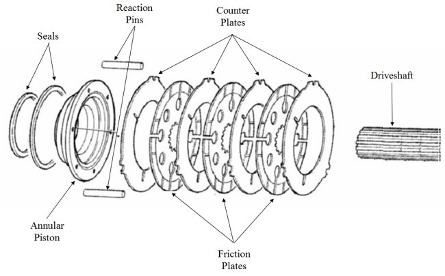
The braking faces are between a number of interleaved friction discs and counter
plates alternately keyed to the housing or splined to a driveshaft. The plates
are clamped together to produce a braking torque either by an annular piston
which is coaxial with the driveshaft or by a ball and ramp mechanism.
Many vehicles using this type of brake have hub reduction gearing so it is common
for oil immersed brakes to be inboard of this gearing and as such they run at
five or six time wheel speed.
Annular Piston Brakes
Annular piston brakes have the benefit of simplicity of construction.
As the piston only moves in an axial direction to load the brake plates there
is no inbuilt servo effect and the brake factor is one. A low brake factor means
that the brake torque between left and right brakes will be more equal (since
differences are not amplified) and the brake system will be more controllable,
for a similar actuation.
On the downside, to get a given torque output a bigger piston will be required
and this together with the long rubber seals (one metre or more) consumes a
greater fluid volume. In order to minimise pedal travel, in none power brake
applications, annular piston brakes run with low clearances and often have a
method of controlling the amount of piston retraction.
Generally this type of brake is manufactured ‘in house’ with only
the plates being bought from a specialist brake supplier.
Ball Ramp Brakes
Ball ramp brakes have a mechanism inside the axle however if they are hydraulically applied the actuation is usually accessible from outside which helps to reduce servicing costs. In order to make a ball ramp actuator non servo the actuator must be decoupled from the friction plates. This is best done by using a needle roller bearing but Yamaha use a low friction plain bearing on this ATV brake as an acceptable trade off between performance and simplicity.
Drag Losses
The main difference between a brake and a clutch is that a brake
runs open and a clutch closed. In a brake the clearance between the plates causes
parasitic losses by churning the oil and can consume large amounts of power,
(the same applies to a lesser extent on ventilated dry discs where air pumping
losses can be considerable – The French TGV train runs on solid discs
for this reason).
Power losses reduce as the clearance increases up to about 0.15mm per face but
at this level the fluid volume required to apply the brake would make actuation
difficult.
Running Clearance Control
Running clearances are usually compromises between minimising
power losses and reasonable pedal travels when controlled by a master cylinder.
Power loss curves shows little benefit can be gained from increasing the clearance
above 0.15mm per friction face.
Annular piston brakes often use a controlled back-off mechanism to ensure the
running clearance is maintained as plate wear takes place. This usually consists
of a spring and a friction device.
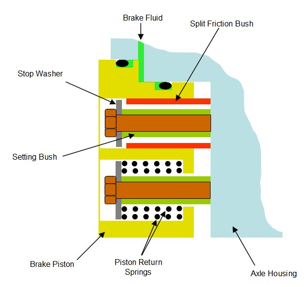
This is a part section of a Caterpillar annular piston brake showing
one of the, usually three retraction devices.
When the brake is applied brake fluid pressurises the annular area between the two seals and forces the brake
piston to the left, clamping the friction plates to the counter plates
(not shown). If no adjustment is required then the split
friction bush pressed into the brake
piston does not contact the stop washer.
Releasing the brake pressure allows the piston
return springs to reset the brake piston until the end of the split friction bush touches the axle housing.
Should adjustment be required the split friction
bush touches the stop washer before sufficient clamp load is generated on the friction plates, this causes
the split friction bush to be dragged
down its bore. When the brake is released the brake
piston is reset to a new back stop position.
This type of adjuster is not load insensitive and could over-adjust if a high
pressure stop allowed the piston to move beyond its normal position however
given the brake is a full circle and the friction material is very thin the
brake is so stiff as to not require a more complex adjuster.
Friction Material Type
There are four basic types of friction material available each with there own pro’s and cons, sintered, paper, graphitic, carbon.
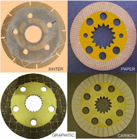
Sintered bronze is made by sintering a blend of powders into a
porous matrix on a steel carrier plate. It is a tough durable material well
able to live with overheating. On the downside it has a low dynamic friction
and a high static / dynamic friction ratio which can cause chatter noise.
Paper frictions materials are so called because of the manufacturing process
as much as the material itself. They contain a range of fibres and friction
modifiers which are then saturated in resins. The resulting material is soft
and easily damaged. Paper materials have a high dynamic friction level and a
low static / dynamic friction ratio which gives them good torque capacity and
low noise however their energy capacity tends to be low.
Graphitic materials are moulded compositions of graphite and resin binders.
The have good thermal capacities which make them durable however they have a
moderate static / dynamic friction ratio which may make them noisy.
Carbon linings give stable friction, high load and low wear but are very expensive
as such they are rarely used.
Groove Pattern
Grooves are either machined or moulded into the friction material
to aid oil flow and thus cooling. Numerous patterns exist and each friction
plate manufacturer has his favourite however the following points should be
born in mind:-
The oil must be part of the cooling process. If large amounts of oil are present
then the oil can flow quickly through the plates however if supply is limited
then the flow through the plates should be restricted. Oil trapped between plates
increases the parasitic drag losses and causes oil heating during brakes off
running.
Spiral - This grooving pattern may be used where there is limited oil available
due to the design of the brake. The spiral pattern gives controlled oil
flow through the grooves but will give high viscous drag.
Radial - or sunburst pattern is suitable for applications in which sufficient
oil is available. It facilitates high oil flow and quickly disperses heat
whilst minimizing viscous drag.
Waffle - or multiple pass patterns are compromises between spiral and radial
and offer some oil flow restriction without increasing drag too much.
© Engineering Inspiration