Repeat the process for the trailing shoe. Remember to draw the lining mu line towards the abutment not the cylinder. The overall brake factor is the sum of the two shoe factors.
  |
| Acres Geometry |
(FREDERICK ALBERT) STEPNEY ACRES proposed a graphical method for drum brake design whilst working for Vauxhall Motors in 1946. It quickly allows the centre of pressure and brake factor to be calculated and being graphical gives a visual perspective to what's happening.
To see how to construct Acres Geometry, click on each step in turn.
| Step> |
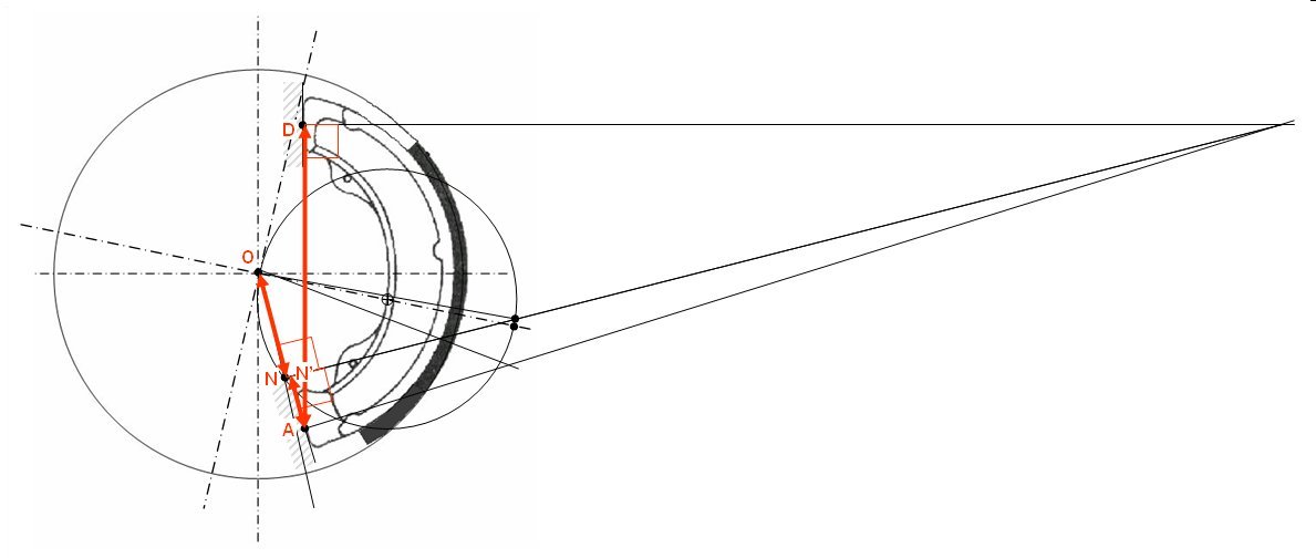
Calculate the shoe factor from:-
SF =
AD/r x ON/AN'
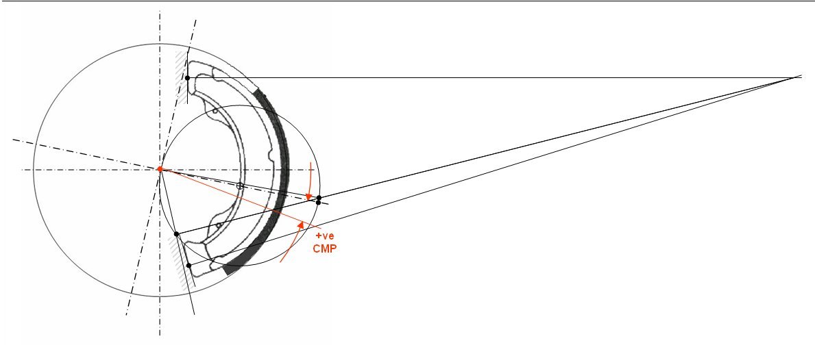
Calculate the Centre of Maximum Pressure
angle (CMP):-
CMP = arctan(tan(EOZ) / c)
where:
c= ((α-½.sin(2α) / (a+½Sin(2α)
and
α = half the lining arc angle (rads)
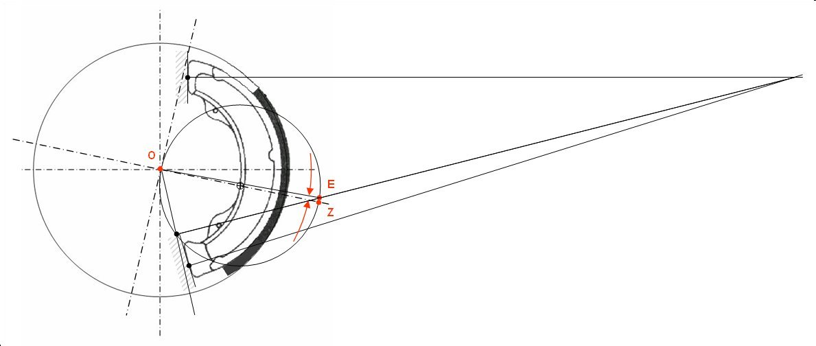
Measure the angle EOZ
Join the point where the shoe reaction crosses the base circle to the origin.
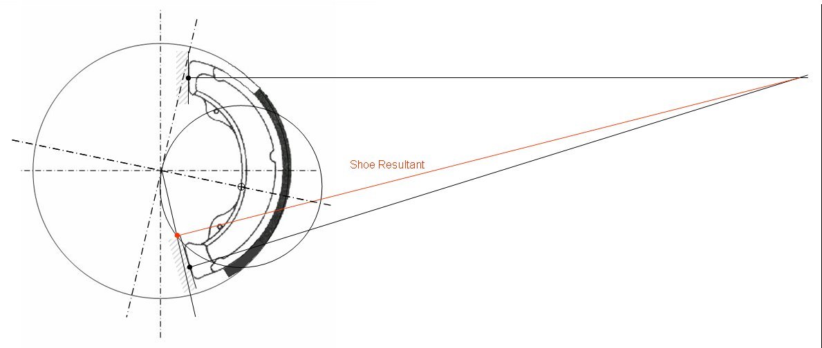
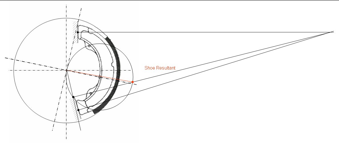
Draw in the shoe resultant line from the point where the abutment and cylinder results cross to the point where the lining mu line crosses the base circle.
Repeat the process for the trailing shoe. Remember to draw the lining mu line towards the abutment not the cylinder. The overall brake factor is the sum of the two shoe factors.
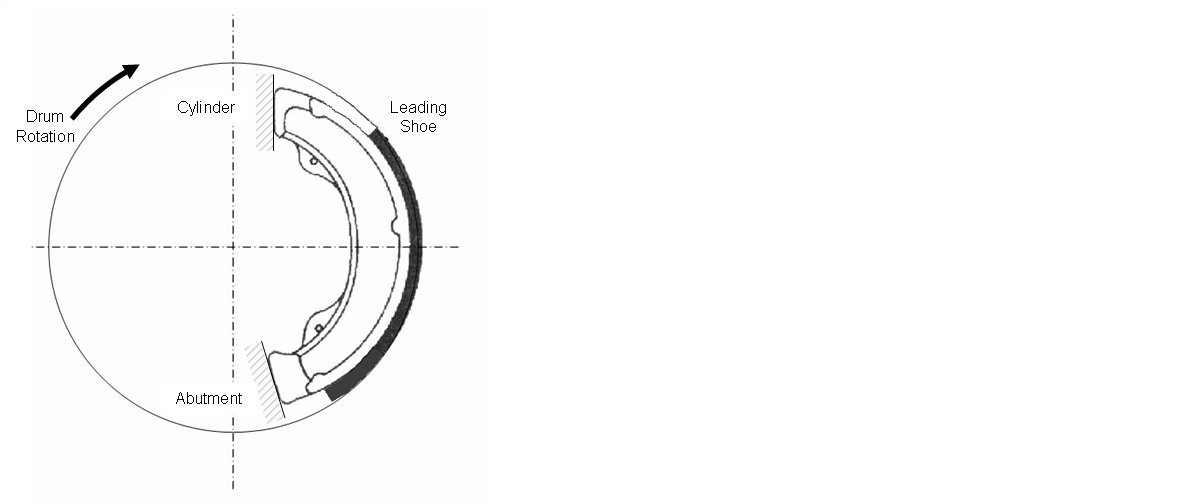
Start off by drawing the leading shoe, the abutment and the wheel cylinder as shown. Mark on some arbitrary centre lines and the drum rotation direction.
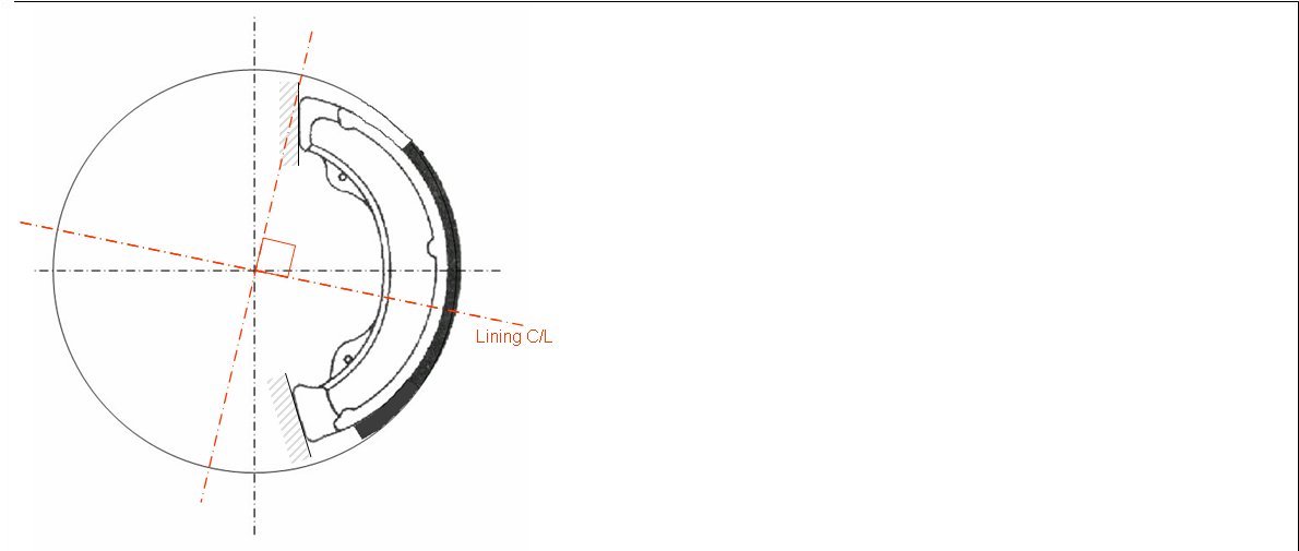
Draw in the lining centre line and a centre line perpendicular to it.
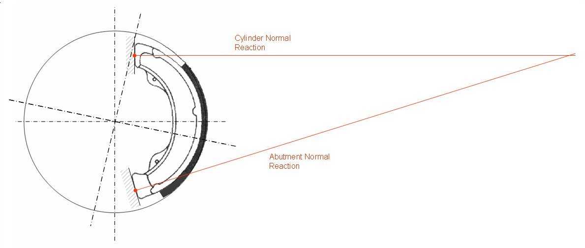
Draw reaction lines perpendicular to the wheel cylinder and abutment contact points to a point where they cross.
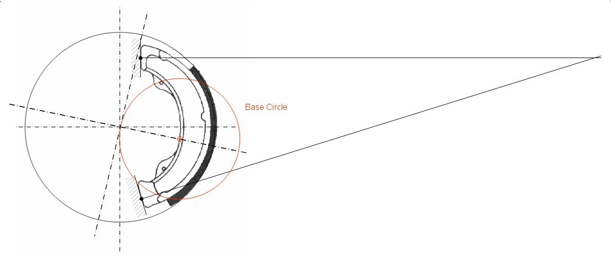
Calculate the diameter of the base circle:-
Dia = (2.r.sin(α)) / (α+½Sin(2α)
where:
r = drum radius (mm)
α = half the lining arc angle (rads)
Draw it passing through the origin and centred on the lining centre line.
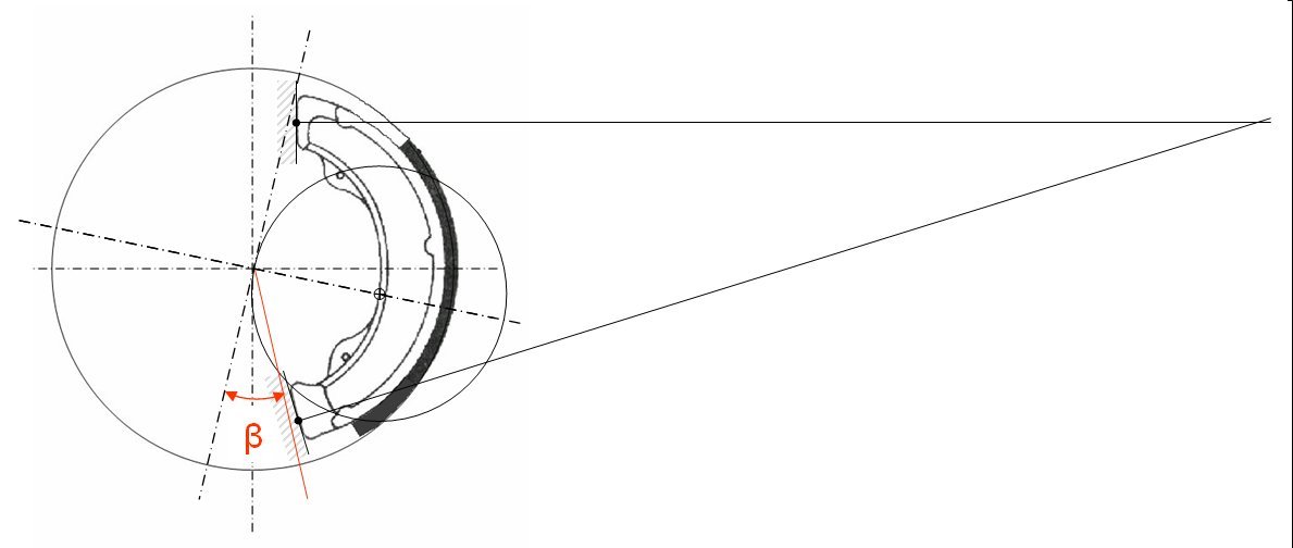
Calculate the lining mu angle using :-
β= arctan(lining mu)
Draw it from the origin towards the abutment.
© Engineering Inspiration